Thermoelectric Sample-Cooling System Assembly
A block diagram of the cooling system is shown in Figure 1.
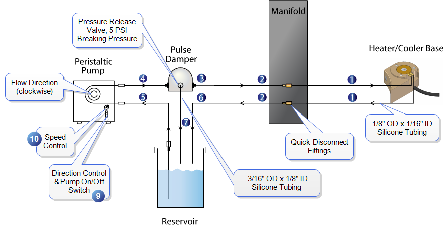
Figure 1: Sample Cooling System. D3100/V base shown. Numbers correspond to steps below.
Connect the cooling system as follows (the steps correspond to the numbers in Figure 1, above):
- Install the shorter dual tubing assembly from the two fluid quick-disconnect couplings on the front of the manifold to the barb fittings on the magnetic base.
NOTE: These Colder Products Company (CPC) quick-disconnect couplings on the manifold are both fluid and gas-compatible and include a spring-operated 316 SS valve that seals the flow path when fitting halves are disengaged.
- Route the hoses through the clamps (attached with thumb screws) on the top of the manifold to provide a service loop, shown in Figure 2 and Figure 3. Ensure that sufficient slack exists to provide travel to all four corners of the stage travel. The two markers on the tubes should be on each side of the cable clamps on the top of the manifold.
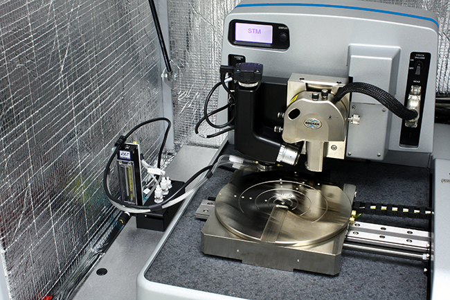
Figure 2: Run water and gas cables through clamps on top of manifold to provide a service loop.
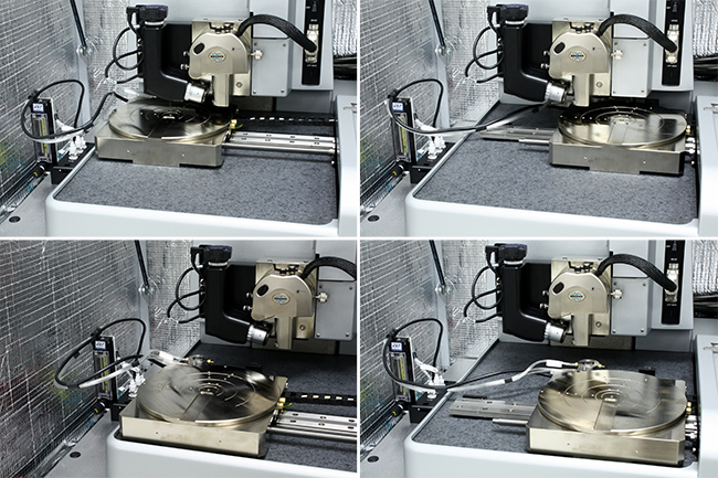
Figure 3: Cable routing at extremes of stage travel.
- Place the water and gas lines on the stand-off holding the heater/cooler to the Dimension Icon chuck base (see figure .
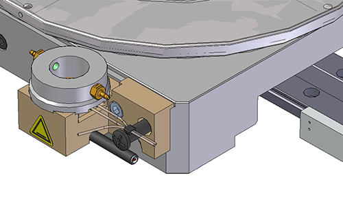
Figure 4: Place the water and gas lines on the stand-off
- Install the longer dual tubing assembly from the two (fluid) quick-disconnect couplings on the back of the manifold (see Figure 5).
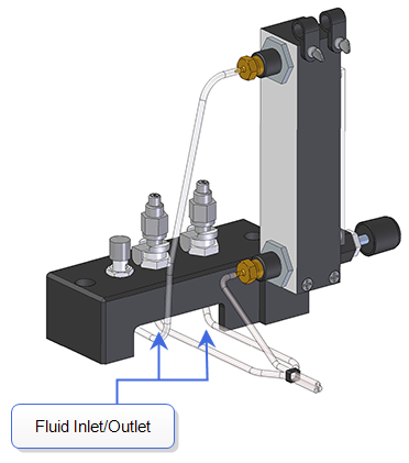
Figure 5: Manifold - rear view.
- Connect one of the tubes from the rear of the manifold to one end of the pulse damper.
- Connect a short line from the pulse damper to the peristaltic pump.
- Connect the other short line from the peristaltic pump to the CPC quick-disconnect fitting on the reservoir bottle labeled Pump.
- Connect the second long line from the back of the manifold (see Figure 5) to the reservoir bottle.
- Connect a 3/16” OD line from the unlabeled reservoir bottle connection to the pulse damper.
- Fill the reservoir bottle approximately 3/4 full with distilled, filtered water.
- Toggle the pump switch to On so that the fluid flows from the reservoir to the pump, through the pulse damper and into the magnetic base. Allow the pump to run until all the lines are filled with water and drips appear on the output side of the reservoir bottle connector. This takes a few minutes. The reservoir bottle fluid level should remain at a constant height once the cooling circuit has been primed. The reservoir bottle remains about half full once the circuit is full.
NOTE: The pulse damper greatly reduces mechanical noise from the peristaltic pump.
- Start with the lowest pump speed (full counter-clockwise knob setting). Increase the pump speed as needed to keep the reservoir temperature low. Sample cooling, which transfers heat from the sample to the reservoir, will generally require higher pump speeds than heating.
NOTE: Speeds greater than 1/3 maximum generally do not improve sample cooling but only add noise to the system.
| www.bruker.com
|
Bruker Corporation |
| www.brukerafmprobes.com
|
112 Robin Hill Rd. |
| nanoscaleworld.bruker-axs.com/nanoscaleworld/
|
Santa Barbara, CA 93117 |
| |
|
| |
Customer Support: (800) 873-9750 |
| |
Copyright 2010, 2011. All Rights Reserved. |
Open topic with navigation